
In today’s connected world, physical network cables are increasingly becoming a legacy technology. From smartphones and tablets to laptops and smart devices, modern computing relies almost entirely on wireless networking.
At its core, wireless networking allows devices to join local networks and access the internet using radio waves instead of physical copper or fiber cables. To keep communication seamless across billions of devices worldwide, the networking industry relies on a unified set of rules known as the IEEE 802.11 standard family—more commonly known as Wi-Fi.
Here is a complete breakdown of how wireless networking operates, how Wi-Fi standards evolved over time, and how individual data frames travel through the air.
1. How Wireless Signals Travel: Frequency Bands
Radio communications operate across specific slices of the electromagnetic spectrum called frequency bands. For example, standard FM radio in North America broadcasts within the 88 MHz to 108 MHz range.
Wi-Fi networks primarily rely on two main unlicensed frequency bands:
- 2.4 GHz Band: Provides longer range and penetrates solid objects (like walls and floors) effectively. However, it suffers from heavy congestion because household items like microwaves, Bluetooth devices, and baby monitors share the same frequency space.
- 5 GHz Band: Offers significantly faster data transfer speeds and less signal interference due to a broader set of channels. Its primary downside is a shorter range and weaker penetration through physical obstacles.
2. The Evolution of IEEE 802.11 Wi-Fi Standards
Since its inception, the IEEE 802.11 committee has continuously updated specifications to boost throughput, lower latency, and accommodate higher device density.
| Standard | Wi-Fi Branding | Year Introduced | Frequency Band | Maximum Theoretical Speed | Key Advancement |
| 802.11b | Wi-Fi 1 | 1999 | 2.4 GHz | 11 Mbps | First mainstream consumer wireless standard (DSSS modulation). |
| 802.11a | Wi-Fi 2 | 1999 | 5 GHz | 54 Mbps | Introduced OFDM modulation; higher speeds with reduced distance. |
| 802.11g | Wi-Fi 3 | 2003 | 2.4 GHz | 54 Mbps | Combined 802.11a speed with 2.4 GHz coverage; backward-compatible with 802.11b. |
| 802.11n | Wi-Fi 4 | 2009 | 2.4 GHz / 5 GHz | 600 Mbps | Introduced MIMO (Multiple Input Multiple Output) multi-antenna technology. |
| 802.11ac | Wi-Fi 5 | 2013 | 5 GHz | ~6.9 Gbps | Introduced MU-MIMO, beamforming, and wider 80 MHz/160 MHz channels. |
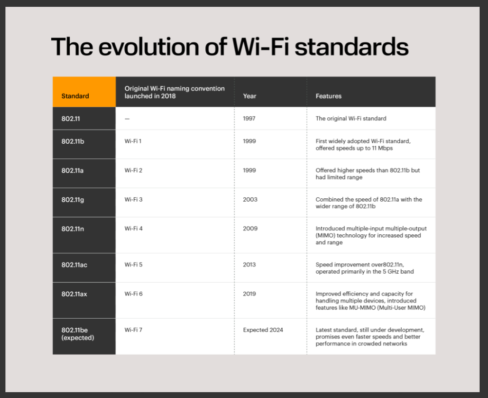
The evolution of WiFi standards

I generated different a sheet with WiFi technology from 1999 all the way to 2024
with the help of Google Gemini: https://share.gemini.google/rlHfGmwgAavQ
802.11 Frame Structure Breakdown
In the OSI model, 802.11 standards operate across both the Physical Layer (Layer 1) and Data Link Layer (Layer 2). Below is how an 802.11 MAC frame is structured from left to right:

- Frame Control (2 bytes / 16 bits): Contains flags for protocol version, frame type (Management, Control, or Data), frame subtype, and control flags (such as To DS and From DS to indicate distribution direction).
- Duration / ID (2 bytes): Tells receiving devices how many microseconds the medium will be busy so they defer transmission (NAV – Network Allocation Vector).
- Address 1 (6 bytes): Receiver Address (RA) / Destination Address.
- Address 2 (6 bytes): Transmitter Address (TA) / Source Address.
- Address 3 (6 bytes): Filtering address (often the BSSID / Access Point MAC address or original source).
- Sequence Control (2 bytes): Contains sequence and fragment numbers to reassemble segmented data and filter duplicate frames.
- Address 4 (6 bytes): Used primarily in Wireless Distribution System (WDS) mesh scenarios where frames are bridged wirelessly between multiple Access Points.
- QoS Control / HT Control (Optional, 2 bytes): Added in 802.11e/n for traffic prioritization (voice/video).
- Frame Body (Payload, 0–2312 bytes): The higher-layer packet data (e.g., IP packet).
Address 2 (6 bytes): Transmitter Address (TA) / Source Address.
Address 3 (6 bytes): Filtering address (often the BSSID / Access Point MAC address or original source).
Sequence Control (2 bytes): Contains sequence and fragment numbers to reassemble segmented data and filter duplicate frames.
Address 4 (6 bytes): Used primarily in Wireless Distribution System (WDS) mesh scenarios where frames are bridged wirelessly between multiple Access Points.
QoS Control / HT Control (Optional, 2 bytes): Added in 802.11e/n for traffic prioritization (voice/video).
Frame Body (Payload, 0–2312 bytes): The higher-layer packet data (e.g., IP packet).
10. Frame Check Sequence (FCS, 4 bytes): A 32-bit Cyclical Redundancy Check (CRC) used to detect errors or corruption over the air.
Why Are There 4 MAC Addresses?
Unlike standard Ethernet (which only requires Source MAC and Destination MAC), wireless frames must track both the end stations and the intermediate wireless access points handling the transmission over the air.
- Destination Address (DA): Final recipient of the frame.
- Source Address (SA): Original generator of the frame.
- Receiver Address (RA): Immediate wireless access point or client listening to the RF transmission.
- Transmitter Address (TA): Immediate wireless device transmitting the RF signal.
3. How 802.11 Works in the OSI Model
In standard networking models, the IEEE 802.11 specification operates across two bottom layers:
- Physical Layer (Layer 1): Governs radio wave transmission, signal encoding, and radio frequency modulation.
- Data Link Layer (Layer 2): Handles MAC addressing, frame creation, channel access, and error detection.
4. Inside an 802.11 Wireless Frame Header
Unlike an Ethernet frame (which primarily uses just a source MAC address and a destination MAC address), an 802.11 wireless frame carries extra control fields to coordinate over-the-air communication.

An 802.11 MAC frame consists of the following fields:
- Frame Control (2 bytes / 16 bits): Describes how the frame must be processed. It includes flags for protocol version, frame type (Management, Control, or Data), and routing flags (To DS and From DS).
- Duration / ID (2 bytes): Informs surrounding wireless devices how long the RF channel will be occupied so they can defer transmissions to prevent collisions.
- Address 1 through 4 (6 bytes each / 24 bytes total): MAC address fields that identify all intermediate and destination endpoints (detailed below).
- Sequence Control (2 bytes): Tracks frame ordering and fragment numbers to ensure packets are reassembled correctly and duplicates are dropped.
- QoS Control / HT Control (Optional): Prioritizes real-time traffic such as voice calls or video streams.
- Data Payload (Variable): Contains the upper-layer network protocol data (such as an IP packet).
- Frame Check Sequence (FCS / 4 bytes): Contains a Cyclical Redundancy Check (CRC) checksum that detects bit corruption during transmission.
5. Why Does an 802.11 Frame Need Four MAC Address Fields?
Standard wired Ethernet uses two addresses (Source MAC and Destination MAC). In contrast, wireless networks rely on devices called Access Points (APs) to bridge traffic between the wireless radio medium and the wired backbone network.
Because wireless devices pass data through intermediate access points or relay nodes, 802.11 defines four separate address slots:
- Destination Address (DA): The ultimate end recipient of the data.
- Source Address (SA): The original device that generated the data.
- Receiver Address (RA): The immediate wireless access point or client receiving the RF signal.
- Transmitter Address (TA): The immediate wireless node transmitting the RF signal over the air.
In standard home setups, the Transmitter Address matches the Source Address, and the Receiver Address matches the Destination Address. However, when frames travel through repeater setups or mesh access points (Wireless Distribution Systems / WDS), all four address fields become active to track the intermediate hops along the way.
Expanded Blog Post Section: Wi-Fi 6, Wi-Fi 6E & Beyond## 6. The Modern Era: Wi-Fi 6 (802.11ax) and Wi-Fi 7 (802.11be)As density in urban environments and smart homes surged, the IEEE standard evolved beyond raw peak speeds toward **spectral efficiency and multi-device capacity**.* **802.11ax (Wi-Fi 6 / 2019):** Designed for high-density environments. It operates across both 2.4 GHz and 5 GHz bands and introduces key cellular-like technologies: * **OFDMA (Orthogonal Frequency-Division Multiple Access):** Splits individual channels into smaller sub-carriers ("resource units"), allowing a router to talk to multiple client devices simultaneously in a single transmission window. * **TWT (Target Wake Time):** Allows IoT devices to negotiate when to wake up and send data, dramatically improving device battery life. * **Wi-Fi 6E (2021):** Extends Wi-Fi 6 operations into the brand-new, uncontested **6 GHz frequency band**, adding up to 1,200 MHz of additional spectrum free from legacy device interference.* **802.11be (Wi-Fi 7 / 2024):** The newest generation built for ultra-low latency and extreme throughput (up to 46 Gbps). Key innovations include: * **320 MHz Channels:** Doubles the channel bandwidth in the 6 GHz spectrum. * **4096-QAM (4K-QAM):** Encodes 12 bits per symbol (up from 10 bits in Wi-Fi 6), increasing data transfer rates by 20%. * **MLO (Multi-Link Operation):** Allows a single device to send and receive data across multiple bands simultaneously (e.g., 5 GHz and 6 GHz at the same time) for near-zero latency and high redundancy.


Geef een reactie